Object: Orientation of Total Station and its Temporary Adjustment.
Apparatus:
Total Station, Tripod, Prism
THEORY:
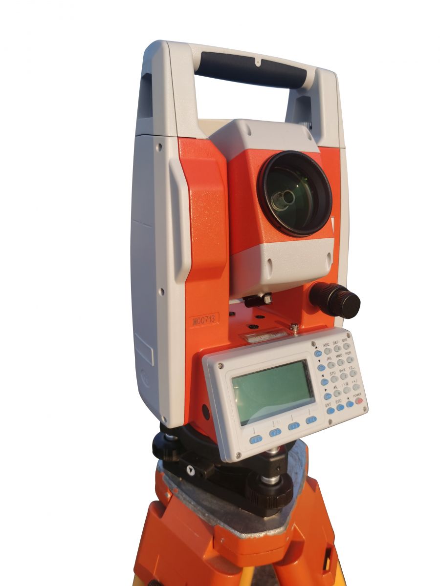
A total station (TS) or total station theodolite (TST) is an electronic/optical instrument used for surveying and building construction. It is an electronic transit theodolite integrated with electronic distance measurement (EDM) to measure both vertical and horizontal angles and the slope distance from the instrument to a particular point, and an onboard computer to collect data and perform triangulation calculations.

Robotic or motorized total stations allow the operator to control the instrument from a distance via remote control. In theory, this eliminates the need for an assistant staff member as the operator holds the retroreflector and controls the total station from the observed point. In practice, however, an assistant surveyor is often needed when the surveying is being conducted in busy areas such as on a public carriageway or construction site. This is to prevent people from disrupting the total station as they walk past, which would necessitate resetting the tripod and re-establishing a baseline. Additionally, an assistant surveyor discourages opportunistic theft, which is not uncommon due to the value of the instrument. These motorized total stations can also be used in automated setups known as Automated Motorized Total Station (AMTS).

Functions of a total station:
- Angle measurement
- Distance measurement
- Coordinate measurement
- Data processing
Procedure:
Orientation of Total Station and Its Adjustment
Total Station is a modern surveying instrument that integrates electronic distance measurement (EDM), an electronic theodolite, and a microprocessor. Before using a Total Station for precise measurements, it must be properly oriented and adjusted.
1. Orientation of Total Station
Orientation in surveying refers to establishing a reference direction for angular measurements. The Total Station must be aligned correctly to ensure accurate readings. The following methods are used for orientation:
1.1. Known Point Orientation (Resection)
- If two or more known points are available in the field, the Total Station can determine its position using resection.
- Steps:
- Setup the Total Station over an unknown point.
- Sight and measure angles/distances to at least two known control points.
- The instrument calculates its position using triangulation.
1.2. Back Sight (BS) Orientation
- This method is used when a reference point (back sight) is known.
- Steps:
- Set up the Total Station at a control point.
- Level the instrument properly.
- Aim at a known back sight point and enter its coordinates.
- The instrument calculates orientation and adjusts readings accordingly.
1.3. Azimuth Orientation
- The Total Station is oriented to a predefined azimuth or bearing.
- Steps:
- Establish a known azimuth direction.
- Align the instrument with that direction.
- Lock the azimuth setting for subsequent measurements.
2. Adjustment of Total Station
Proper adjustment ensures accurate readings. The main adjustments include:
2.1. Centering
- The instrument must be precisely placed over the survey station using a plumb bob or optical plummet.
- Steps:
- Adjust the tripod legs to position the instrument over the survey marker.
- Fine-tune using the tribrach’s leveling screws.
2.2. Leveling
- The Total Station must be perfectly horizontal.
- Steps:
- Use the built-in circular bubble or electronic level.
- Adjust leveling screws until the bubble is centered.
2.3. Collimation Error Check
- Ensures that the telescope’s line of sight is properly aligned.
- Steps:
- Sight a distant point and note the reading.
- Rotate the telescope 180° and check if the same point is aligned.
- If misaligned, adjust using the collimation correction setting.
2.4. EDM Calibration
- The EDM function should be tested for distance measurement accuracy.
- Steps:
- Measure a known baseline.
- Compare the measured distance with the actual distance.
- Apply corrections if needed.
3. Importance of Proper Orientation and Adjustment
- Reduces errors in surveying measurements.
- Improves accuracy for construction, topographic, and geodetic surveys.
- Ensures consistency in fieldwork.
Details of improving orientation accuracy of total station
Coordinate orientation of a total station is a necessary work for coordinate staking out and point position measurement in construction surveys. Accidental errors can be reduced during coordinate staking out and point measurement through multiple alignment measurements, and fixed errors can be reduced through left and right disk observation, to improve measurement accuracy. However, due to the special properties of the total station, the orientation of the total station can only be determined once. If the view orientation error is 5 “, there is a high probability that you will also have an error of 5 “at all measuring points at this station. Ensuring the accuracy of orientation is the basic premise to ensure the accuracy of staking out points and measuring points.
According to our years of measurement experience, attention to details and measures for the directional accuracy of the total station are summarized as follows:
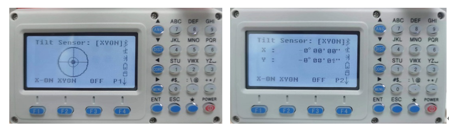
1. Calibrate the compensator before orientation
The compensator of the total station usually needs to be calibrated frequently. Before observation, the total station should rotate 90°, 180°, 270° to check the compliance of the compensator. When the deviation is found to be large, it can be immediately calibrated in the field, which generally takes only several minutes.
2. Calibration instrument alignment axis error
Alignment axis error, also known as 2C error, affects the horizontal angle. This error can be eliminated by observing the left 1&2 and taking the median, but it is not appropriate to do that when measuring point position and coordinate staking out. Therefore, the instrument 2C error should be adjusted as small as possible in advance. We generally consider it safe to calibrate it to less than 2 seconds. It doesn’t need to be often corrected if there is no big turbulence.
How to calibrate the alignment axis error: https://youtu.be/W2Mdi7NB0ls
3. Verify the center and stability of bubbles before orientation
Usually, when arriving at the control point, the surveyor will first centralize and level the total station. However, when the total station is set up for the first time, distance orientation generally takes time for a while, such as waiting for the prism to arrive at the measuring point, input the station and back sight point coordinates, etc. The time generally takes several minutes to more than ten minutes. During this period, the instrument bubbles will generally have different degrees of deviation because the total station is just set up, the foot is not stable enough, the instrument is just adapting to the outside temperature, or the surveyor will walk around the instrument. Therefore, the electronic bubble adjustment interface should be opened again to re-check and adjust the electronic bubble after the station coordinates and the view coordinates are set up, and the instrument telescope is aiming at the back sight point direction. The small movements will not affect the instrument alignment accuracy; don’t worry about it.
4. Aim repeatedly at the back sight point to determine orientation
A better way to manually aim at the back sight point is to zoom in on the observation target repeatedly (you can also aim at the center of the prism if the distance is relatively close). When you feel the best alignment, press the “Record” key of the instrument.
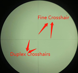
Many surveyors like to aim at the bottom of the pole for fear that its perpendicularity is not good enough, which is fine, but WE usually don’t because we always have the perpendicularity of the pole calibrated in advance. If the verticality of the older pole is uncertain, or when the pole needs to be extended relatively high, you can also aim at the bottom of the pole through the gap. The crosshairs of total station telescopes have two types: duplex crosshairs and fine crosshairs. Fine crosshair is generally used to aim. However, when aiming at the bottom of the pole, we can generally jam the target with duplex crosshairs, so that it will be more accurate.
5. Remeasurement after orientation
It is necessary to remeasure the coordinates of back sight points after orientation, and the coordinate and elevation values of the retest should be recorded completely and compared with the design results.
Experienced surveyors can judge the backtracking error, which is the observer’s alignment error or control point error, according to the directional azimuth angle.