To cast reinforced concrete beams for determining the flexural strength.
STANDARDS:
ASTM C78-02
THEORY:
Difficulties in determining Tensile Strength of Concrete:
There are considerable experimental difficulties in determining the flexural strength of concrete beam. In flexural test following are the difficulties:
1. When beam is gripped by the machine it may be crushed due the large stress concentration at the grip.
2. Concrete samples of different sizes and diameters show large variation in results.
3. If there are some voids in sample the test may show very small strength.
4. If there is some initial misalignment in fixing the sample the results are not accurate
Modulus of Rupture:
In a flexural test on a reinforced concrete specimen, the maximum tensile stress reached at the bottom fiber of a standard size prism (beam) under predefined loading type is called modulus of rupture.
Type / Size Of The Specimen For The Test:
The specimen used is a prism, square in cross-section and having a certain length. There are two standard sizes of the specimen that can be used for specified aggregate sizes.
1. 3’ x 6” x 6”
The size ( 3’ x 6” x 6” ) can be used for all sizes of the aggregate particles.
PROCEDURE:
- Take mix proportion as 1:2:4 with water cement ratio of 0.5.
- Design the reinforcement with suitable mould size
- Then fix the reinforcement in the mould
- Calculate the required quantity for the standard mould.
- Weigh the required amount of cement ,sand ,fine and coarse aggregate and water.
- Start the mixer machine .put the aggregates (coarse and fine aggregate) and half of the water in mixer.
- After homogenous mixture of aggregates ,put the cement and remaining water.
- Mix it until homogenous mixture is obtained.
- Put the concrete of the machine and place it in the formwork of the beam.
- During placing it should be compacted through rod ix) (mould should be oiled)
QUANTITY CALCULATION:
Mix Proportion 1:2:3
W/C 0.5
Density= 145lb/ft3
Dimensions of the beam 3’ x 6” x 6”
OBJECTIVE :- TO DETERMINE FLEXURAL STRENGTH OF REINFORCED CONCRETE
Standards :- IS: 516–1959 – Methods of tests for strength of concrete
Apparatus :-
- Beam mould
- Tamping bar
- Flexural testing machine
Procedure :-
- Prepare the test specimen by filling the concrete into the mould in 3 layers of approximately equal thickness. Tamp each layer 35 times using the tamping bar as specified above. Tamping should be distributed uniformly over the entire crossection of the beam mould and throughout the depth of each layer.
- Clean the bearing surfaces of the supporting and loading rollers , and remove any loose sand or other material from the surfaces of the specimen where they are to make contact with the rollers.
- Circular rollers manufactured out of steel having cross section with diameter 38 mm will be used for providing support and loading points to the specimens. The length of the rollers shall be at least 10 mm more than the width of the test specimen. A total of four rollers shall be used, three out of which shall be capable of rotating along their own axes. The distance between the outer rollers (i.e. span) shall be 3d and the distance between the inner rollers shall be d. The inner rollers shall be equally spaced between the outer rollers, such that the entire system is systematic.
- The specimen stored in water shall be tested immediately on removal from water; while they are still wet. The test specimen shall be placed in the machine correctly centered with the longitudinal axis of the specimen at right angles to the rollers. For moulded specimens, the mould filling direction shall be normal to the direction of loading.
- The load shall be applied at a rate of loading of 400 kg/min for the 15.0 cm specimens and at a rate of 180 kg/min for the 10.0 cm specimens.
Calculation :-
The Flexural Strength or modulus of rupture (fb) is given by
fb = pl/bd2 (when a > 20.0cm for 15.0cm specimen or > 13.0cm for 10cm specimen)
or
fb = 3pa/bd2 (when a < 20.0cm but > 17.0 for 15.0cm specimen or < 13.3 cm but > 11.0cm for 10.0cm specimen.)
Where,
a = the distance between the line of fracture and the nearer support, measured on the center line of the tensile side of the specimen
b = width of specimen (cm)
d = failure point depth (cm)
l = supported length (cm)
p = max. Load (kg)
Result :-
The Flexural strength of the concrete is reported to two significant figures.
- Safety and Precautions :-
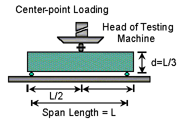
OBJECT: To Determine The Flexural Strength Of Plain Concrete By Center Point Loading Method.
STANDARDS:
ASTM C293-02 6.2
SCOPE:
This test method covers the determination of the flexural strength of concrete by the use of a simple beam with third-point loading.
APPARATUS LOADING APPARATUS:
Beam Mould , Trowel, Weighing Balance, Mould oil or Grease Flexure Testing Machine etc.
MATERIALS COARSE AGGREGATES:
Fine Aggregates, Cement, Mould Oil or Grease.
PROCEDURE:
1. Flexural tests of moist-cured specimens shall be made as soon as practical after removal from moist storage. Surface drying of the specimen results in a reduction in the measured flexural strength.
2. When using molded specimens, turn the test specimen on its side with respect to its position as molded and center it on the support blocks.
3. Center the loading system in relation to the applied force. Bring the load-applying blocks in contact with the surface of the specimen at the third points and apply a load of between 3 and 6 % of the estimated ultimate load.
4. Using 0.004 in. (0.10 mm) and 0.015 in. (0.38 mm) leaf-type feeler gages, determine whether any gap between the specimen and the load-applying or support blocks is greater or less than each of the gages over a length of 1 in. (25 mm) or more.
5. Grind, cap, or use leather shims on the specimen contact surface to eliminate any gap in excess of 0.004 in. (0.10 mm) in width. Leather shims shall be of uniform 1⁄4 in. (6.4 mm) thickness, 1 to 2 in. (25 to 50 mm) width, and shall extend across the full width of the specimen.
6. Gaps in excess of 0.015 in. (0.38 mm) shall be eliminated only by capping or grinding. Grinding of lateral surfaces should be minimized inasmuch as grinding may change the physical characteristics of the specimens.
7. Apply the load at a rate that constantly increases the extreme fiber stress between 125 and 175 psi/min (0.86 and 1.21 MPa/min), when calculated in accordance with 8.1, until rupture occurs. The loading rate is calculated using the following equation: r = 2Sbd2/L Where,
r = loading rate, lb/min [MN/min]
S = rate of increase in extreme fiber stress, psi/min (MPa/min),
b= average width of the specimen, in.(mm),
d= average depth of the specimen, in. (mm), and
L= span length, in. (mm).
To determine the dimensions of the specimen cross section for use in calculating modulus of rupture, take one measurement at each edge and one at the center of the cross section to determine the average width and the average depth.

CALCULATION:
The fracture initiates in the tension surface within the middle third of the span length, calculate the modulus of rupture as follows:
R = 3PL/2bd2
Where, R = modulus of rupture, psi or MPa.
P = maximum applied load indicated by the testing machine, lbf, or N,
L = span length, in., or mm.
b = average width of specimen, in,.or mm, at fracture , and
d = average depth of specimen, in., or mm, at the fracture.
PRECAUTIONS:
1. Surface drying of the specimen results in the measured flexural strength.
2. Load the specimen continuously and without shock.
3. Results of two properly conducted tests by the same operator on beams made from the same batch sample should not differ from each other by more than 12%.
- Use hand gloves while, safety shoes at the time of test.
- After test switch off the machine.
- Keep all the exposed metal parts greased.
- Keep the guide rods firmly fixed to the base & top plate.
- Equipment should be cleaned thoroughly before testing & after testing.
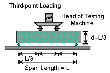
OBJECT: To Determine The Flexural Strength Of Plain Concrete By Third Point Loading Method.
STANDARDS:
ASTM C 78
SCOPE:
This test method covers the determination of the flexural strength of concrete by the use of a simple beam with third-point loading.
APPARATUS LOADING APPARATUS:
Beam Mould , Trowel, Weighing Balance, Mould oil or Grease Flexure Testing Machine etc.
MATERIALS COARSE AGGREGATES:
Fine Aggregates, Cement, Mould Oil or Grease
PROCEDURE:
1. Flexural tests of moist-cured specimens shall be made as soon as practical after removal from moist storage. Surface drying of the specimen results in a reduction in the measured flexural strength.
2. When using molded specimens, turn the test specimen on its side with respect to its position as molded and center it on the support blocks.
3. Center the loading system in relation to the applied force. Bring the load-applying blocks in contact with the surface of the specimen at the third points and apply a load of between 3 and 6 % of the estimated ultimate load.
4. Using 0.004 in. (0.10 mm) and 0.015 in. (0.38 mm) leaf-type feeler gages, determine whether any gap between the specimen and the load-applying or support blocks is greater or less than each of the gages over a length of 1 in. (25 mm) or more.
5. Grind, cap, or use leather shims on the specimen contact surface to eliminate any gap in excess of 0.004 in. (0.10 mm) in width. Leather shims shall be of uniform 1⁄4 in. (6.4 mm) thickness, 1 to 2 in. (25 to 50 mm) width, and shall extend across the full width of the specimen.
6. Gaps in excess of 0.015 in. (0.38 mm) shall be eliminated only by capping or grinding. Grinding of lateral surfaces should be minimized inasmuch as grinding may change the physical characteristics of the specimens.
7. Apply the load at a rate that constantly increases the extreme fiber stress between 125 and 175 psi/min (0.86 and 1.21 MPa/min),
when calculated in accordance with 8.1, until rupture occurs.
The loading rate is calculated using the following equation:
r = Sbd2/L Where,
r = loading rate, lb./min [MN/min]
S = rate of increase in extreme fiber stress, psi/min (MPa/min),
b= average width of the specimen, in.(mm),
d= average depth of the specimen, in. (mm), and
L= span length, in. (mm).
To determine the dimensions of the specimen cross section for use in calculating modulus of rupture, take one measurement at each edge and one at the center of the cross section to determine the average width and the average depth.

- Flexural strength is measured by modulus of rupture.
Equation to calculate this is as follows:
R=(PL/bd2)
where:
R = modulus of rupture, MPa [psi],
P = maximum applied load indicated by the testing machine, N [lbf],
L = span length, mm [in.],
b = average width of specimen, mm [in.], at the fracture, and
d = average depth of specimen, mm [in.], at the fracture