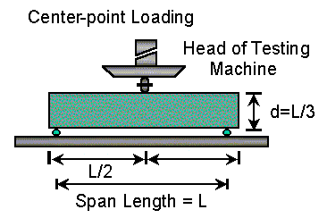
OBJECT: To Determine The Flexural Strength Of Plain Concrete By Center Point Loading Method.
STANDARDS:
ASTM C293-02 6.2
SCOPE:
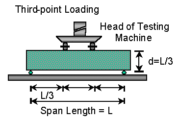
This test method covers the determination of the flexural strength of concrete by the use of a simple beam with third-point loading.
APPARATUS LOADING APPARATUS:
Beam Mould , Trowel, Weighing Balance, Mould oil or Grease Flexure Testing Machine etc.
MATERIALS COARSE AGGREGATES:
Fine Aggregates, Cement, Mould Oil or Grease.
PROCEDURE:
1. Flexural tests of moist-cured specimens shall be made as soon as practical after removal from moist storage. Surface drying of the specimen results in a reduction in the measured flexural strength.
2. When using molded specimens, turn the test specimen on its side with respect to its position as molded and center it on the support blocks.
3. Center the loading system in relation to the applied force. Bring the load-applying blocks in contact with the surface of the specimen at the third points and apply a load of between 3 and 6 % of the estimated ultimate load.
4. Using 0.004 in. (0.10 mm) and 0.015 in. (0.38 mm) leaf-type feeler gages, determine whether any gap between the specimen and the load-applying or support blocks is greater or less than each of the gages over a length of 1 in. (25 mm) or more.
5. Grind, cap, or use leather shims on the specimen contact surface to eliminate any gap in excess of 0.004 in. (0.10 mm) in width. Leather shims shall be of uniform 1⁄4 in. (6.4 mm) thickness, 1 to 2 in. (25 to 50 mm) width, and shall extend across the full width of the specimen.
6. Gaps in excess of 0.015 in. (0.38 mm) shall be eliminated only by capping or grinding. Grinding of lateral surfaces should be minimized inasmuch as grinding may change the physical characteristics of the specimens.
7. Apply the load at a rate that constantly increases the extreme fiber stress between 125 and 175 psi/min (0.86 and 1.21 MPa/min), when calculated in accordance with 8.1, until rupture occurs. The loading rate is calculated using the following equation: r = 2Sbd2/L Where,
r = loading rate, lb/min [MN/min]
S = rate of increase in extreme fiber stress, psi/min (MPa/min),
b= average width of the specimen, in.(mm),
d= average depth of the specimen, in. (mm), and
L= span length, in. (mm).
To determine the dimensions of the specimen cross section for use in calculating modulus of rupture, take one measurement at each edge and one at the center of the cross section to determine the average width and the average depth.

CALCULATION:
The fracture initiates in the tension surface within the middle third of the span length, calculate the modulus of rupture as follows:
R = 3PL/2bd2
Where, R = modulus of rupture, psi or MPa.
P = maximum applied load indicated by the testing machine, lbf, or N,
L = span length, in., or mm.
b = average width of specimen, in,.or mm, at fracture , and
d = average depth of specimen, in., or mm, at the fracture.
PRECAUTIONS:
1. Surface drying of the specimen results in the measured flexural strength.
2. Load the specimen continuously and without shock.
3. Results of two properly conducted tests by the same operator on beams made from the same batch sample should not differ from each other by more than 12%.
PRACTICAL NO 08
OBJECT: To Determine The Flexural Strength Of Plain Concrete By Third Point Loading Method.
STANDARDS:
ASTM C 78
SCOPE:
This test method covers the determination of the flexural strength of concrete by the use of a simple beam with third-point loading.
APPARATUS LOADING APPARATUS:
Beam Mould , Trowel, Weighing Balance, Mould oil or Grease Flexure Testing Machine etc.
MATERIALS COARSE AGGREGATES:
Fine Aggregates, Cement, Mould Oil or Grease
PROCEDURE:
1. Flexural tests of moist-cured specimens shall be made as soon as practical after removal from moist storage. Surface drying of the specimen results in a reduction in the measured flexural strength.
2. When using molded specimens, turn the test specimen on its side with respect to its position as molded and center it on the support blocks.
3. Center the loading system in relation to the applied force. Bring the load-applying blocks in contact with the surface of the specimen at the third points and apply a load of between 3 and 6 % of the estimated ultimate load.
4. Using 0.004 in. (0.10 mm) and 0.015 in. (0.38 mm) leaf-type feeler gages, determine whether any gap between the specimen and the load-applying or support blocks is greater or less than each of the gages over a length of 1 in. (25 mm) or more.
5. Grind, cap, or use leather shims on the specimen contact surface to eliminate any gap in excess of 0.004 in. (0.10 mm) in width. Leather shims shall be of uniform 1⁄4 in. (6.4 mm) thickness, 1 to 2 in. (25 to 50 mm) width, and shall extend across the full width of the specimen.
6. Gaps in excess of 0.015 in. (0.38 mm) shall be eliminated only by capping or grinding. Grinding of lateral surfaces should be minimized inasmuch as grinding may change the physical characteristics of the specimens.
7. Apply the load at a rate that constantly increases the extreme fiber stress between 125 and 175 psi/min (0.86 and 1.21 MPa/min),
when calculated in accordance with 8.1, until rupture occurs.
The loading rate is calculated using the following equation:
r = Sbd2/L Where,
r = loading rate, lb./min [MN/min]
S = rate of increase in extreme fiber stress, psi/min (MPa/min),
b= average width of the specimen, in.(mm),
d= average depth of the specimen, in. (mm), and
L= span length, in. (mm).
To determine the dimensions of the specimen cross section for use in calculating modulus of rupture, take one measurement at each edge and one at the center of the cross section to determine the average width and the average depth.

- Flexural strength is measured by modulus of rupture.
Equation to calculate this is as follows:
R=(PL/bd2)
where:
R = modulus of rupture, MPa [psi],
P = maximum applied load indicated by the testing machine, N [lbf],
L = span length, mm [in.],
b = average width of specimen, mm [in.], at the fracture, and
d = average depth of specimen, mm [in.], at the fracture